Calculations
The length of an antenna is based upon the formula C =l*f
Where:
There are other phenomena to take into account: one is air effects at the ends of the antenna and another is Velocity of propagation (V.P.)
End effects reduce the antenna length by about 5 %. VP depends upon the material surrounding the antenna conductor and is 100 % where air is concerned. However, if the antenna is embedded within the structure, say glass fibre, or is coated with an insulating material, the VP is less than 100 %. This is also relevant in the construction of baluns where, for example, the VP for cellular polyethylene insulation is 78 %.
Fortunately, the dipole antennas described have "broad-band" characteristics and the length is not too critical. In any case a non-tunable antenna is, strictly speaking, at maximum efficiency for one frequency only. Hence it is usual to choose mid-band frequency for calculations. Any departure from the correct theoretical antenna length will merely favor one half of the frequency band more than the other.
Therefore for antennas, reduce the length by 5 % for end effects, if surrounded by air, and by up to 20 %, if insulated or embedded. Many VOR and some COM antennas are made of stainless steel, uncoated and mounted externally. These are classed as being surrounded by air.
Typical antenna lengths for mid-band frequency are as follows:
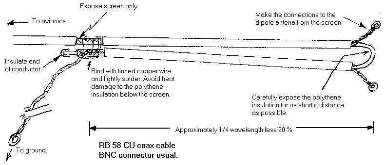
Dipole antennas require no ground plane. They are, in effect, two 1/4 wave antennas mounted end-to-end, about 5 to 10 mm apart, with the feed taken from the center. However, because the antenna has balanced feed characteristics and the feeder cable characteristics are usually unbalanced, then a BALUN is necessary. This can consist of electronic circuitry, ferrite torroids or, as described later, made from the feeder cable.
The feeder cable in aircraft is usually RG58U. This cable is of the coax type and has an impedance of 50 Ohms, a stranded conductor and the insulation is non-contaminating. A stranded conductor is more flexible and less susceptible to breakage than a solid conductor. These features far outweigh the slight decrease in signal strength. Cheaper cable should not be used, as the quality of the screen is usually the first to suffer.
Antennas can be made from a variety of materials. Stainless steel is common, but difficulty in soldering can create problems for the home constructor. Self adhesive copper foil, such as is used in staines glass work, is excellent for embedded antennas. It is easy to solder and form around contours if necessary and is available in various widths. An effective ground plane can also be made by using 4 to 6 intersecting 1/4 wave lengths of the foil. Another material is the conductors, complete with the inner insulation, from out of a 2.5 mm grade mains cable. Simply cut the cable to length, remove the outer sheath and there are two halves of a dipole: one brown and the other blue (or black).
Making a BALUN

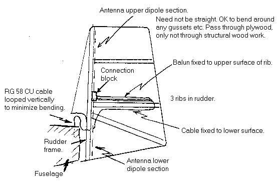
COM antenna for D11
Thinking of recovering your rudder? then also consider one of these antennas. Perhaps 5 kt more airspeed if you remove your old one ?


Discard the outer sheath - usually grayish in color. Leave the conductors inside their insulation, usually blue and brown.


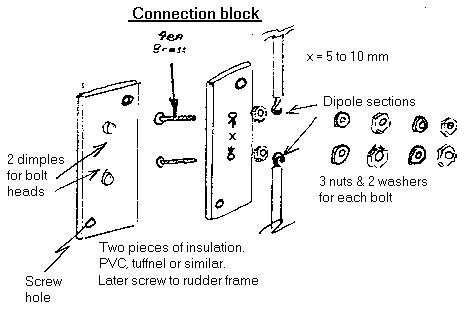
Bolt the insulator. Tighten first nuts. Attach dipoles and solder. Add washer nuts and one more nut to each. Attach balun with remainder of washers and nuts. Make secure. Weather- and damp-proof with an insulating non-setting sealant or could possibly use one of the silicones.
Note: Type of antenna and position: AD917 approval required from PFA.
If you have any comments, please contact ![]() ping@piteraq.dk
ping@piteraq.dk
| Back to previous page | Back to Ping's Homepage |